Yagi-Uda antenna
In the 1926, Dr. Shintaro Uda and Dr. Hidetsugu Yagi of the Tohoku Imperial University invented a directional antenna system consisting of an array of coupled parallel dipoles.
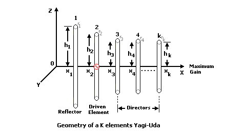
The geometry of the Yagi-Uda array:

The second dipole in the Yagi-Uda array is the only driven element with applied input/output source feed, all the others interact by mutual coupling since receive and reradiate electromagnetic energy; they act as parasitic elements by induced current. It is assumed that an antenna is a passive reciprocal device, then may used either for transmission or for reception of the electromagnetic energy: this well applies to Yagi-Uda also.
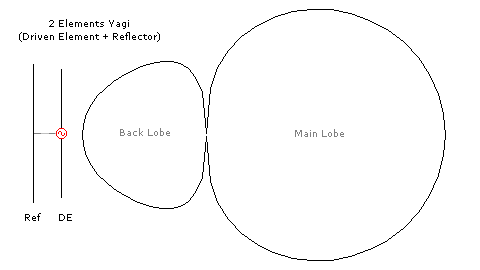
The simplest or minimal Yagi-Uda antenna has at least two parasitic elements behind the Driven Element (DE); the antenna with only one parasitic element as Reflector element (Ref) is generally called Yagi antenna. This happens when the electrical length of the parasitic element is greater than the driven element.

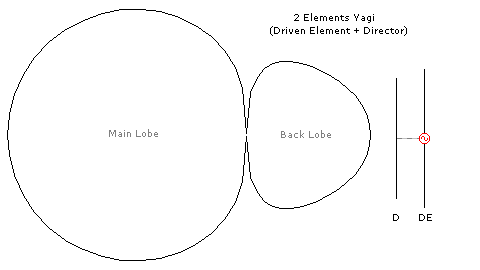
If the electrical length of the parasitic element is shorter than the driven element, the radiation pattern reversed and the parasitic element became a Director (D) always in the two-elements of the Yagi antenna.

FAQ's: what does the antenna difference between Yagi-Uda and Yagi? A television set antenna, FM and amateurs radio beam, a lot of WiFi and satellite antennas are not the Yagi?
Answer: Yagi-Uda is the correct complete name for any antenna with three or more elements in the array. Yagi is the name for the two elements, a driven element and the reflector, or the driven element and one director alone. Yagi is well-accepted term for any linear end-fire array like the Yagi-Uda defined above. The television antenna set, FM and amateur radio antennas commonly named Yagi are really Yagi-Uda antenna when three or more elements in the system array. The two terms seems to be equivalent in the common practical use. Yagi-Uda should be the historically correct name. Yagi Antenna has Patent Number 69115 in Japan.
[ Yagi-Uda basics ]
[ index page ] [ basics 1 ] [ basics 2 ] [ measure ] [ acronym and definitions ] [ sample/repository: ] [ 3 elements Yagi-Uda ] [ 4 elements Yagi-Uda ] [ 5 elements Yagi-Uda ] [ 6 elements Yagi-Uda ] [ 7 elements Yagi-Uda ] [ 8 elements Yagi-Uda ] [ 9 elements Yagi-Uda ] [ 10 elements Yagi-Uda ] [ 11 elements Yagi-Uda ] [ Coaxial Balun ] [ Link to us; Free code ] [ Terms of use; Disclaimer; Privacy policy ] [ site map; contents ]
Copyright © 2008 Yagi-Uda.com, All Rights Reserved.
Created Date: Sat, 12 Apr 2008 10:10:01 z by Yagi-Uda.com
Last modified Date: December 01, 2011 17:32:08 z by Yagi-Uda.com